Why Swimming Pool Shell Removal Is a Diamond Tooling Problem First and a Demolition Problem Second
Most homeowners and even some general contractors look at a gunite or shotcrete pool shell and see a jackhammer job. Senior concrete cutting professionals see something entirely different — a multi-phase cutting operation that requires matched equipment tonnage, diamond segment geometry, and a cut sequencing plan before a single blade ever touches the shell wall. When you’re hired to remove a swimming pool in the Miami-Dade metro, the variables stack up fast: shell thickness ranging from 6 to 12 inches, dense rebar grids in the walls and floor, post-tension tendons in adjacent deck slabs, and water table conditions that affect both blade cooling and spoil management. Get the tooling wrong and you’re burning through $800 blades, cracking adjacent hardscape, and blowing your labor budget before noon.
Pool Shell Composition and What It Means for Blade Segment Specification
Gunite and shotcrete pools built in South Florida between 1975 and 2005 typically present with a compressive strength range of 4,000 to 6,500 PSI, occasionally higher in commercial installations. That hardness range sits in the mid-tier for diamond tooling, but the real complication is the reinforcement matrix. Pool walls carry #4 and #5 rebar on 12-inch centers both horizontally and vertically, and the floor slab typically runs #4 on 18-inch centers with a 3.5- to 4-inch cover. What this creates is a material that oscillates between relatively soft aggregate and hard steel at a frequency that punishes the wrong diamond segment bond.
For this application, the correct diamond blade specification is a hard-bond, high-diamond-concentration segment — specifically a segment matrix rated for medium-to-hard concrete with steel reinforcement. A soft-bond segment will shed diamonds prematurely against the rebar, and an ultra-hard bond won’t self-dress properly in the cured gunite matrix. The industry standard for this work is a 14-inch to 18-inch diameter blade with a 0.140- to 0.160-inch kerf, laser-welded segments at 2.5-inch height, and a segment count that provides adequate gullet spacing for slurry evacuation. Turbo rim geometry is acceptable for wall cuts; continuous rim is not appropriate here at any diameter.
Flat Saw Configuration for Pool Floor Demolition Grid Cutting
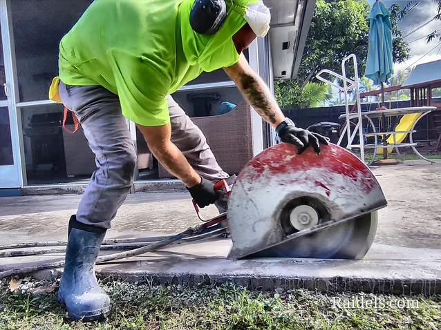
The pool floor is where flat sawing earns its keep. A properly configured flat saw setup allows the operator to grid-cut the floor slab into manageable sections — typically 24-inch by 36-inch panels — that an excavator thumb or concrete pulverizer can extract cleanly without fragmenting into unmanageable rubble. The equipment spec for this phase starts with a walk-behind flat saw in the 35- to 65-horsepower range, belt-driven or direct-drive, capable of sustaining blade RPM under load in the 2,200 to 2,800 range.
Blade diameter selection for floor cutting is driven by the slab thickness plus the required cut depth. A 6-inch pool floor requires a minimum 14-inch blade to achieve full-depth penetration with a standard flat saw arbor height. An 8-inch floor steps you up to an 18-inch blade. In either case, the blade must be mounted on a machine with sufficient horsepower to maintain peripheral blade speed — typically 14,000 to 16,000 surface feet per minute — without bogging under the load of cutting through rebar. Underpowered machines cause blade wobble, segment side-loading, and premature core failure. This is not a place to deploy a rental-grade saw.
Water delivery is non-negotiable. Minimum flow rate for an 18-inch blade in this application is 3.5 gallons per minute at the blade flanges, delivered through the blade guard ports. Anything less and you’re running dry, which means thermal stress cracking in the segments and a blade that glazes over within two linear feet of cutting. For projects in Miami job sites with tight access constraints, a self-contained water recirculation system mounted on the saw eliminates the need for a dedicated water line and keeps slurry contained for vacuum recovery.
Wall Demolition Sequencing and the Case for Ring Saw Over Angle Grinder Cuts
Pool wall removal presents a different geometry problem than floor cutting. Walls are vertical, curved in most residential pools, and vary in thickness from the waterline tile band (often 6 inches) down to the deep end transition (commonly 10 to 12 inches). The curved geometry eliminates conventional flat saw use entirely. The two viable cutting methods are hand-held ring saw and diamond wire saw, with the selection driven by wall thickness and site access.
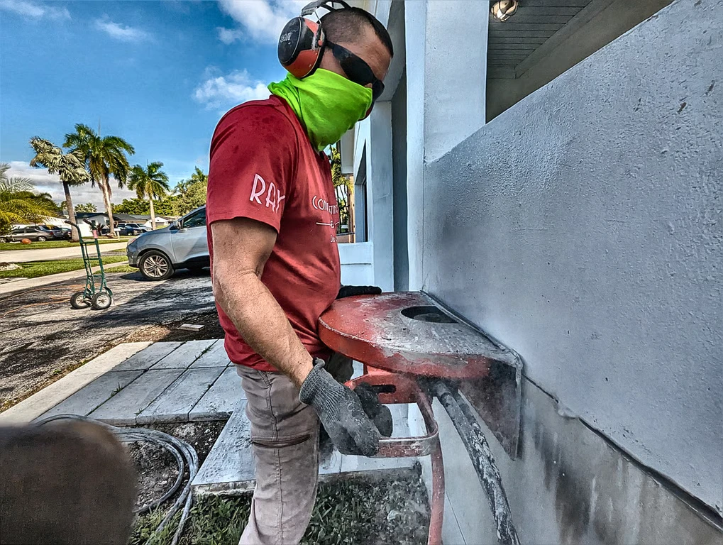
For walls under 10 inches, a ring saw with a 14-inch cutting ring and a hydraulic or electric power unit in the 5 to 7 kW range is the correct tool. Ring saws offer a cutting depth of approximately 10 inches from a single-sided approach, which covers most residential pool wall sections. The blade specification here mirrors the floor cutting recommendation — hard bond, laser-welded segments, turbo geometry — but the ring saw platform demands a blade specifically profiled for the ring saw arbor, not a converted flat saw blade. Segment height on ring saw blades typically runs 0.120 to 0.135 inches due to the tighter radius geometry.
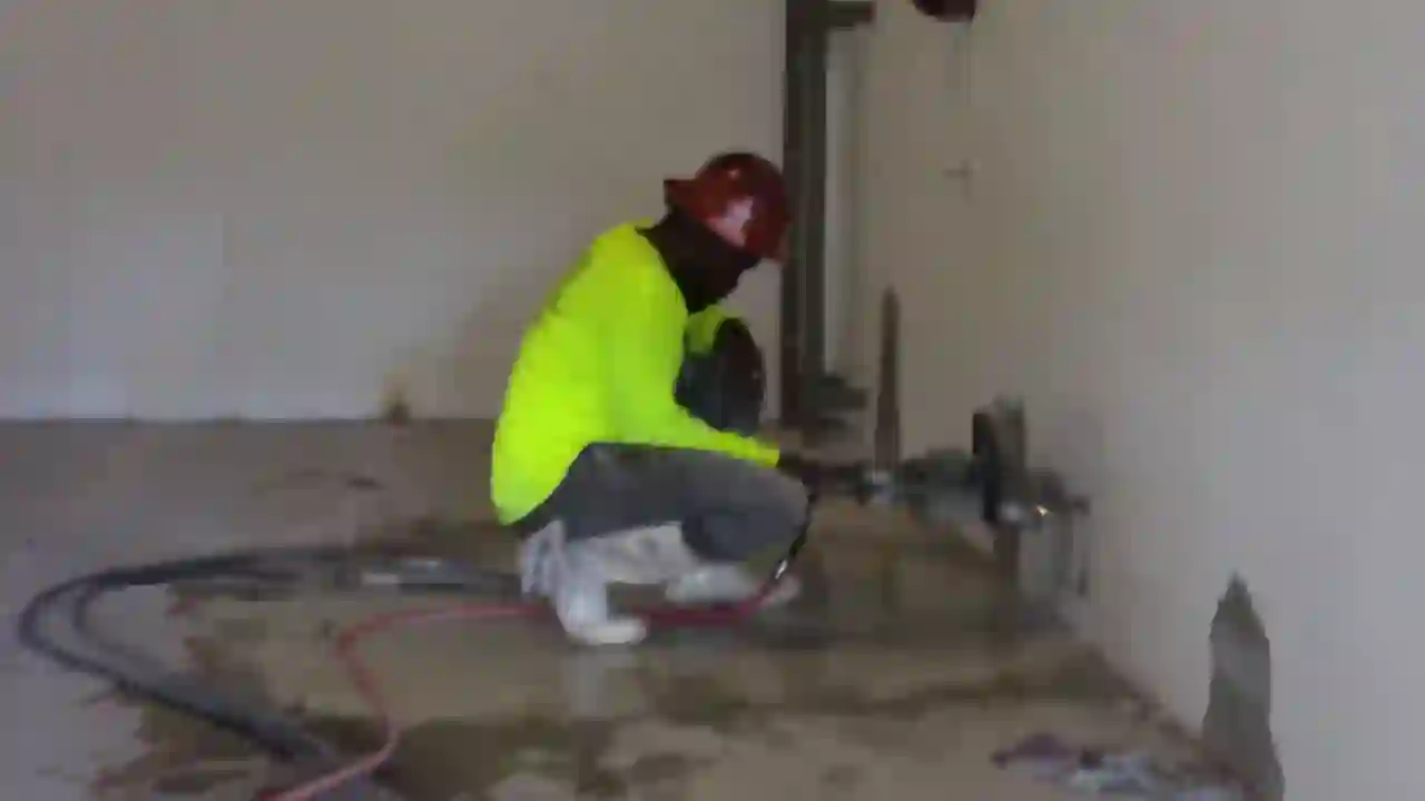
For walls exceeding 10 inches, or for situations where the pool shell abuts a structure that cannot tolerate vibration, diamond wire saw becomes the technically correct answer. Wire diameter for reinforced concrete pool walls runs 8.0 to 10.5 mm, with diamond bead spacing of 25 to 40 beads per meter depending on aggregate hardness. The wire saw machine must maintain wire tension in the 200 to 350 Newton range throughout the cut to prevent wire whip and ensure consistent bead-to-concrete contact. This is the same technology used in post-tension slab cutting operations where blade-induced vibration cannot be introduced into the structural system.
Managing Rebar Density Without Destroying Your Diamond Investment
The rebar grid in a pool shell is dense enough that every cut will encounter steel multiple times per linear foot. This is where operators who don’t understand diamond tooling mechanics start burning through blades at an unsustainable rate. The key principle is segment bond hardness must match the abrasiveness of the host matrix, not the hardness of the steel. Rebar is hard, but it’s also ductile — it doesn’t abrade the diamond bond the way hard aggregate does. What rebar does is create an interrupted cut, which generates impact loading on the segment root.
To manage this, blade selection should prioritize high-tensile-strength segment brazing or laser welding over press-sinter attachment. Laser-welded segments can withstand the impact loading of rebar contact at full cutting depth without segment loss. Press-sintered or silver-soldered segments are not appropriate for this application. For a detailed breakdown of how rebar density affects blade behavior across different concrete slab profiles, the technical discussion at cutting rebar-dense concrete slabs without blade damage covers the mechanics in full.
Excavator Attachment Specifications for Post-Cut Pool Shell Extraction
Once the shell is grid-cut, extraction requires an excavator with a concrete pulverizer or hydraulic thumb matched to the panel size. For 24-inch by 36-inch panels cut from a 6- to 8-inch floor, a 5- to 8-ton excavator with a 12-inch hydraulic thumb provides adequate breakout force without over-stressing the cut panels. Panels that are too large for the thumb force available will fold rather than lift clean, which re-entangles the rebar grid and creates extraction problems.
In concrete removal operations across Opa-Locka and surrounding areas, site access often limits excavator size, which pushes the panel size down to 18 by 24 inches to compensate for reduced breakout force. This increases the total number of cuts required but maintains clean extraction geometry. The trade-off is worth it — a clean extraction prevents rebar tangle, reduces haul weight per lift, and keeps the operation moving at pace.
Deck Slab Removal Adjacent to the Pool Shell
The concrete pool deck is frequently a post-tension slab, particularly in commercial installations and higher-end residential properties built after 1990. Before any cutting begins on the deck, GPR scanning is mandatory to locate tendon paths. Cutting a post-tension tendon without controlled de-tensioning is a life safety issue, not just a tooling issue. The tendon will release stored energy in a fraction of a second, and the results are catastrophic.
For conventional reinforced pool decks, the flat saw approach described for the floor slab applies directly. The full technical protocol for thick deck slab removal, including blade selection tables and equipment tonnage guidance, is covered in depth at the complete guide to thick concrete slab removal. The same principles governing segment bond selection and water delivery rates apply here without modification.
Blade Life Benchmarks and What to Expect on a Full Pool Removal
A realistic blade consumption estimate for a standard 12-by-24-foot residential gunite pool removal in South Florida, using correctly specified tooling, runs as follows. Floor grid cutting with an 18-inch flat saw blade: 1 to 1.5 blades per 100 linear feet of cut in 6- to 8-inch reinforced gunite. Wall sectioning with a 14-inch ring saw blade: 0.75 to 1 blade per full wall perimeter cut at 8-inch depth. These numbers assume correct water delivery, proper RPM maintenance, and a blade specification matched to the material hardness. Deviation from any of those parameters will push consumption higher — sometimes dramatically higher.
The total tooling cost for a properly executed residential pool removal typically runs $400 to $900 in diamond blade consumption, depending on pool size, shell thickness, and rebar density. That number is a controllable variable. Operators who select blades on price rather than specification routinely spend two to three times that amount and still finish with worse cut quality and longer cycle times. The economics of correct blade selection are not subtle — they’re decisive.
Every pool removal project starts with a material assessment, a tooling selection decision, and an equipment configuration plan. Get those three elements right and the demolition phase becomes predictable, fast, and cost-controlled. Get them wrong and you’re problem-solving in the field with a burned blade and a blown schedule.