Why Slurry Management Is Now the Most Critical Part of Any Concrete Cut Operation
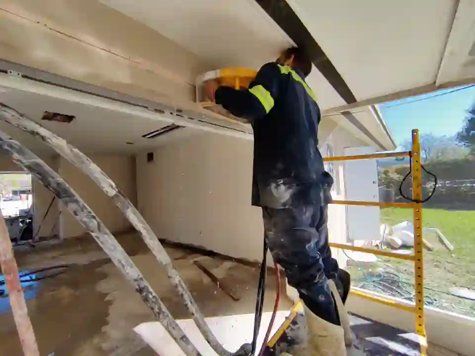
Ask any senior field superintendent in South Florida what’s changed most about concrete cutting over the past decade, and the answer won’t be diamond blade technology or hydraulic power — it’ll be water. Specifically, where the water goes after it contacts a diamond blade mid-cut. Every wet concrete cut produces a gray, alkaline slurry that carries pulverized silica, calcium hydroxide, and trace heavy metals from rebar corrosion byproducts. In Miami-Dade County, discharging that slurry into a storm drain, swale, or any surface water feature is a direct violation of the National Pollutant Discharge Elimination System (NPDES) permit framework — and inspectors are actively writing notices of violation on active construction sites. If you’re managing a project that involves any volume of concrete cutting work, slurry containment is not an afterthought. It is a pre-mobilization deliverable.
The Chemistry Behind Concrete Cut Slurry and Why pH Matters
Concrete slurry is not simply dirty water. When a diamond blade engages a cured slab, the heat and friction liberate calcium oxide and calcium silicate hydrate particles that immediately react with the cooling water stream to form calcium hydroxide — otherwise known as portlandite. This compound drives slurry pH into the range of 11 to 13, making it caustic enough to chemically burn aquatic organisms, destabilize soil microbiology, and corrode metal drainage infrastructure. Miami-Dade’s stormwater management regulations align with Florida Administrative Code Chapter 62-621, which mandates that any construction-related discharge must be treated to a pH between 6.0 and 9.0 before reaching any conveyance system.
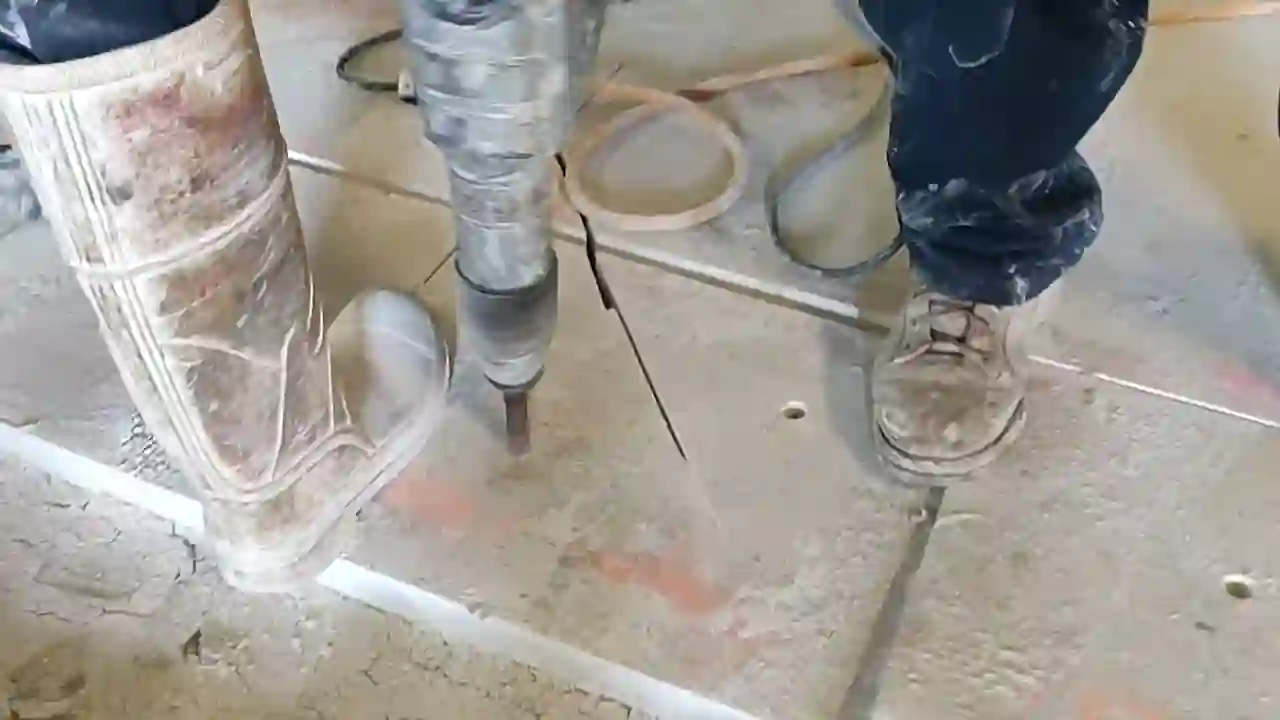
This is not a paperwork technicality. A single floor sawing operation on a 10,000-square-foot slab can generate 40 to 80 gallons of high-pH slurry per hour depending on blade diameter, cut depth, and water feed rate. Multiply that across a multi-day core drilling and wall sawing schedule, and you’re managing hundreds of gallons of regulated waste that requires documented handling, neutralization, and disposal. Understanding this chemistry is the foundation of building a compliant slurry management plan before the first blade spins.
Containment System Design for Slab Sawing and Core Drilling
Effective containment starts with site topography analysis. Before any concrete cut begins, the crew lead should walk the slab or structure and identify all low points, floor drains, expansion joints, and any penetrations that connect to the stormwater system. In Miami’s flat coastal terrain, water moves unpredictably — a seemingly level parking garage deck can have micro-grades that channel slurry toward drains within minutes of cutting starting.
The industry-standard containment approach involves three integrated layers:
- Perimeter berms: Absorbent or rubber-backed berms placed around the entire cutting zone to prevent lateral slurry migration. For interior work, foam backer rod or hydrophilic rubber strips can be pressed into expansion joints to block flow paths.
- Drain plugs and covers: All floor drains within 20 feet of the cutting zone must be plugged with mechanical test plugs or covered with drain guard filters rated for alkaline slurry. Standard rubber plugs are insufficient — use stainless-threaded mechanical plugs for drains that feed directly to the municipal system.
- Vacuum slurry recovery: A wet/dry industrial vacuum with a minimum 20-gallon collection tank should run continuously during cutting, pulling slurry from the kerf and surrounding surface before it can migrate. For larger floor sawing operations, a dedicated slurry vacuum system with 3-inch hose diameter is the appropriate specification.
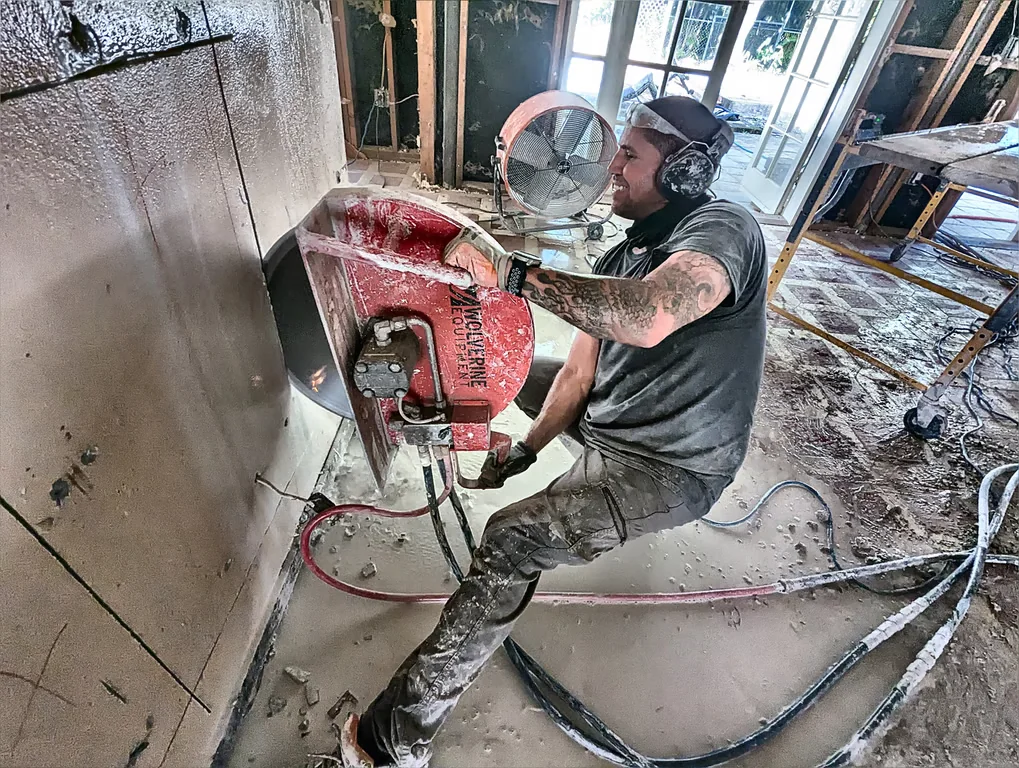
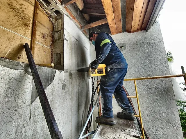
For wall sawing and hydraulic chain saw operations on vertical surfaces, containment becomes three-dimensional. Slurry runs down the wall face and pools at the base — a combination of plastic sheeting, foam backer berm, and a collection trough with vacuum recovery is the accepted best practice for vertical cuts exceeding 12 inches in depth.
Slurry Neutralization Methods Used in Active Miami Jobsites
Once slurry is collected, it must be neutralized before any liquid fraction is discharged or before the solid cake is transported off-site. The two most practical neutralization methods in active field conditions are carbon dioxide injection and dry acid addition.
Carbon dioxide (CO₂) injection is the cleaner, more controllable method. Liquid CO₂ is bubbled through the collected slurry, forming carbonic acid that reacts with calcium hydroxide to produce calcium carbonate — an insoluble, non-hazardous precipitate. pH drops rapidly and predictably, and the process produces no secondary chemical hazards. CO₂ injection systems are available in portable configurations sized for construction site use, and several Miami-area concrete cutting contractors now carry them as standard equipment on larger projects.
Dry acid addition — typically sodium bisulfate or citric acid — is a lower-cost alternative for smaller volumes. The challenge is dosing accuracy: over-acidification drives pH below 6.0, creating a secondary compliance violation. Any dry acid neutralization protocol must include continuous pH monitoring with a calibrated meter, not litmus strips, and the neutralization vessel must provide adequate mixing to ensure uniform treatment throughout the slurry volume.
After neutralization, the solid slurry cake — separated by allowing the neutralized slurry to settle and decanting the clarified water — is classified as a non-hazardous solid waste in Florida, provided the concrete being cut did not contain lead-based paint, asbestos-containing materials, or other regulated constituents. Projects involving pre-1980 concrete should conduct materials testing before any cutting begins, as contaminated slurry cake triggers hazardous waste disposal requirements under RCRA.
Regulatory Documentation and Stormwater Pollution Prevention Plans
In Miami-Dade County, any construction project disturbing more than one acre of land is required to operate under a Stormwater Pollution Prevention Plan (SWPPP) that specifically addresses concrete cutting and saw cutting activities. Even on smaller sites, the contractor performing the concrete cut work may be named as a responsible party under the general contractor’s SWPPP if they are identified as a subcontractor generating process water.
A compliant SWPPP for concrete cutting operations must document the following elements:
- Cutting zone containment diagram showing berm placement, drain plug locations, and slurry recovery equipment positioning
- Slurry volume estimate based on total linear feet of cut, blade diameter, and anticipated water feed rate
- Neutralization protocol with pH target range, monitoring frequency, and responsible personnel designation
- Disposal pathway documentation identifying the licensed facility receiving solid slurry cake and any liquid fraction discharged to sanitary sewer (which requires a separate industrial pretreatment permit in most Miami municipalities)
- Inspection log recording daily visual checks of containment integrity throughout the cutting schedule
Contractors who are also exploring concrete waterproofing in Miami as part of their scope should note that saw-cut joint preparation for waterproofing systems generates the same slurry compliance obligations as structural cutting — the blade diameter is smaller, but the regulatory framework is identical.
Equipment Specifications That Directly Impact Slurry Volume and Compliance Risk
Not all concrete cutting equipment generates slurry at the same rate. Blade selection, water feed system design, and motor power all influence how much process water enters the waste stream per linear foot of cut. Contractors managing tight slurry budgets on urban Miami sites should understand these variables before mobilizing.
Segmented diamond blades with wide gullets between segments evacuate slurry from the kerf more efficiently than continuous-rim blades, reducing the tendency for slurry to accumulate and overflow the cutting zone. For floor sawing, blade diameters above 18 inches should always be paired with a dedicated slurry vacuum rather than relying on gravity drainage to a collection point — the volume rate simply exceeds what passive containment can handle at production cutting speeds.
Water feed rate is the most directly adjustable variable. Many operators run water feeds higher than necessary, believing more water means better blade cooling and longer blade life. In practice, optimized water feed — typically 1.5 to 3.0 gallons per minute for blades up to 14 inches — provides adequate cooling while minimizing slurry generation. Reviewing concrete cutting pricing structures that include slurry management as a line item reflects the true cost of compliant operations, and clients should be educated that low-bid contractors who omit slurry management are externalizing a compliance cost onto the project owner.
Building a Compliant Concrete Cut Program That Holds Up to Inspection
Environmental compliance in concrete cutting is ultimately a systems problem, not an equipment problem. The contractors who consistently pass inspector reviews in Miami-Dade are the ones who have integrated slurry management into their pre-job planning process — not the ones who react when a gray plume reaches the curb. That means pre-mobilization site walks, documented containment plans, calibrated pH meters on every truck, and trained operators who understand why the water matters as much as the blade.
The concrete cut itself is a precise, powerful, and highly controllable operation. The slurry it produces is equally controllable — but only when the crew treats it as a primary deliverable rather than a cleanup afterthought. In South Florida’s regulatory environment, that distinction is the difference between a completed project and a stop-work order.