Why Cutting Concrete Walls Creates a Regulated Waste Stream Most Contractors Underestimate
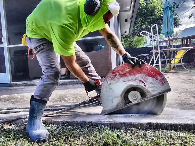
Walk onto almost any concrete wall cutting job in Miami and you’ll see the same scene: a diamond blade spinning at high RPM, a steady stream of cooling water flooding the cut line, and a gray slurry cascading down the wall face and pooling at the base. Most operators are focused on blade depth, feed rate, and wall thickness. What they’re often not focused on — and what can trigger a regulatory violation before the job is even finished — is where that slurry goes. Concrete cutting slurry is not just dirty water. It is a high-pH alkaline waste stream containing suspended silica particulates, cement hydration byproducts, and fine aggregate fines. In Miami-Dade County, discharging that material into storm drains, surface water, or uncontrolled ground areas is a direct violation of NPDES stormwater permit conditions. The environmental exposure is real, and the fines are substantial. Understanding slurry chemistry, containment architecture, and compliant disposal is as technically critical as understanding blade selection or feed pressure.
The Chemistry of Concrete Wall Cutting Slurry and Why pH Matters
When a diamond blade engages a concrete wall, the cooling water immediately begins reacting with freshly exposed calcium silicate hydrate compounds and free lime within the cement matrix. The resulting slurry typically measures between pH 11 and pH 13 — highly caustic by any regulatory standard. For context, the EPA’s Clean Water Act effluent guidelines for construction site discharges require pH levels between 6.0 and 9.0 before any water can be released to a receiving waterway or municipal storm system. That gap between field-generated slurry pH and legal discharge limits is not a minor adjustment. It requires active treatment.
Beyond pH, the suspended solids content in untreated cutting slurry routinely exceeds 1,000 mg/L — far above the 50–80 mg/L threshold that most municipal permits allow for construction site discharge. These suspended particles are predominantly crystalline silica, which carries its own occupational and environmental hazard classification under OSHA’s silica standard (29 CFR 1926.1153). Managing slurry is therefore not a housekeeping task — it is a multi-regulatory compliance obligation touching EPA, OSHA, and local stormwater authorities simultaneously. For more on how our crews approach job site compliance across all phases of concrete work, the technical protocols we follow are documented in detail.
Water Containment Systems Designed Specifically for Vertical Surface Cutting
Horizontal slab cutting has the gravitational advantage — slurry flows to low points and can be directed toward collection sumps with relative ease. Vertical wall cutting is a fundamentally different hydraulic problem. Cooling water is introduced at the blade-wall interface, immediately runs downward along the wall face, and disperses across the floor in an uncontrolled fan pattern unless specific containment infrastructure is pre-installed before cutting begins.
Effective containment for wall cutting operations typically involves a three-layer system:
- Wall-mounted drip channels: Flexible foam-backed dam material adhered directly to the wall face below the cut line, designed to intercept the downward slurry flow and redirect it laterally toward a collection point. These must be staged below every active cut segment, not just at the final cut perimeter.
- Floor containment berms: Deployable rubber or polyurethane berms placed at the base of the wall to prevent floor-level spreading. On uneven substrates, hydraulic putty or foam backer rod fills gap areas that would otherwise allow slurry migration under the berm.
- Wet-vac collection with intermediate settlement tanks: A dedicated slurry vacuum system — not a standard shop vac — pulls collected slurry into a settlement tank where gross solids drop out before the liquid fraction is transferred to a pH treatment vessel. Running a wet-vac directly into a single collection drum without settlement staging leads to rapid solids accumulation that reduces vacuum efficiency and makes final disposal more difficult.
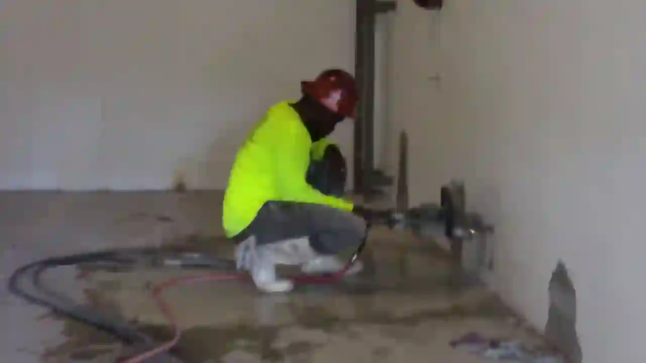
The containment geometry must be planned before the saw is positioned. Once cutting starts, repositioning containment without shutting down the water supply creates exactly the uncontrolled discharge scenario that regulators cite. This is especially relevant on projects involving door enlargements with hydraulic hand saws, where the cut perimeter is irregular and containment geometry must accommodate multiple wall faces simultaneously.

Active pH Neutralization Protocols for On-Site Slurry Treatment
Once slurry is collected and settled, the liquid fraction must be treated before any discharge consideration. The standard field treatment method uses carbon dioxide injection or dilute sulfuric acid addition to drive pH down into the 6.0–9.0 acceptable range. CO₂ injection is the preferred method on occupied or semi-enclosed job sites because it eliminates the chemical handling hazards associated with acid addition and produces no secondary waste byproducts — the reaction simply produces water and calcium carbonate, both inert at the concentrations generated.
The treatment sequence runs as follows:
- Stage 1 — Gross settlement: Allow collected slurry to rest undisturbed in a settlement tank for a minimum of 30 minutes. Solids concentration in the liquid fraction will drop significantly during this window.
- Stage 2 — pH measurement: Test the clarified liquid fraction with a calibrated digital pH meter (not litmus paper — the resolution is insufficient for compliance documentation). Record the initial pH and timestamp.
- Stage 3 — CO₂ injection or acid addition: Introduce treatment agent in metered doses with continuous agitation. Retest pH every 5 minutes until the target range is achieved. Do not overshoot — driving pH below 6.0 creates an acidic discharge condition that is equally non-compliant.
- Stage 4 — Final verification and documentation: Record final pH, treatment agent quantity used, volume of water treated, and disposal method. This documentation is the field evidence that demonstrates compliance if a regulatory inspection occurs.
The solid fraction separated during settlement is typically classified as a non-hazardous solid waste in Florida, provided the concrete being cut does not contain lead-based paint, asbestos-containing materials, or other regulated compounds. Pre-job material characterization — reviewing original construction records or conducting XRF testing on painted wall surfaces — is the due diligence step that determines whether standard disposal applies or whether a hazardous waste manifest is required. Our approach to hazard mitigation on wall cutting projects always begins with this characterization step.
Saw Selection and Water Volume Management for Reduced Slurry Generation
Equipment selection directly affects slurry volume, and lower slurry volume means simpler, lower-cost containment and treatment. This is a point that often gets lost in conversations focused purely on cutting speed or blade life. The relationship between water flow rate, blade diameter, and slurry generation is linear — more water means more slurry to manage. Optimizing water flow to the minimum required for adequate diamond segment cooling reduces slurry output without compromising blade performance or cut quality.
For wall openings up to 24 inches in any dimension, a 20-inch hydraulic hand saw operating at optimized water flow rates generates substantially less slurry per linear foot of cut than a wall saw with a 24-inch or larger blade, simply due to the difference in blade surface area and the corresponding cooling water demand. For larger openings, wall saws are unavoidable, but staged cutting — making multiple passes at increasing depth rather than a single full-depth pass — allows the operator to maintain lower per-pass water volumes while still achieving full penetration. The diamond cutting technology employed determines how aggressively this optimization can be pushed without sacrificing segment bond integrity.
On reinforced walls, the transition from concrete matrix to rebar engagement changes the thermal load on the blade abruptly. Some operators compensate by increasing water flow at rebar encounter points — a practice that spikes slurry generation precisely when the operator is least focused on containment. Training operators to maintain consistent water flow and instead reduce feed rate at rebar encounter points is a better technical and environmental outcome. For projects requiring complete wall or slab removal, the same slurry management discipline applies — as detailed in our coverage of concrete removal projects in Miami.
Regulatory Documentation That Protects the Contractor After the Job Is Done
Miami-Dade County’s Department of Regulatory and Economic Resources (RER) has the authority to inspect active construction sites for stormwater compliance at any time. The contractor’s defense in any enforcement scenario is documentation — not verbal assurances, not photographs alone, but a written slurry management log that records containment deployment, water volumes used, pH test results, treatment agent quantities, and final disposal method for every cutting day.
This log should be formatted to mirror the structure of a Stormwater Pollution Prevention Plan (SWPPP) field record, even on projects that fall below the acreage threshold requiring a formal SWPPP. The discipline of maintaining this documentation does three things: it creates a compliance defense record, it forces the crew to execute the containment and treatment steps consistently, and it builds the institutional knowledge base that allows the operation to scale without regulatory exposure growing proportionally.
For projects in proximity to Biscayne Bay or other Outstanding Florida Waters, the documentation standard should be elevated further — pre-job containment inspection by a qualified person, real-time pH monitoring during cutting operations rather than post-collection testing, and secondary containment backup in case primary systems are overwhelmed by unexpected water volumes from wall voids or embedded conduit.
Building a Slurry Management Protocol That Becomes Standard Operating Procedure
The contractors who consistently avoid regulatory exposure on concrete wall cutting projects are not the ones with the most expensive equipment — they are the ones who have systematized their slurry management approach to the point where it executes automatically on every job, regardless of project size or duration. That means pre-job checklists that include containment material inventory verification, operators trained to identify and respond to containment failures in real time, and project managers who treat the slurry log as a non-negotiable deliverable alongside the cutting completion report.
The technical complexity of cutting concrete walls — blade selection, feed rate optimization, rebar management, structural sequencing — is well understood in the trade. The environmental compliance dimension deserves the same level of technical rigor. Slurry is not a nuisance byproduct. It is a regulated waste stream that, managed correctly, represents a competitive differentiator for contractors who can demonstrate compliance capability to general contractors, owners, and regulators alike. In Miami’s regulatory environment, that capability is increasingly a prerequisite for being awarded the work in the first place.